Sounds like a silly thing, but we all have to start somewhere. Generally when I dig into something new, I like to start from a place I know well. So when it comes to using a new API, I like to use a tool I know how to use. Kubernetes–and its API is fairly new to me from a hands-on perspective. PowerShell, however, is not. I have decent handle on that. So seems to me a good place to start with the k8s API.
I don’t know if this is the best way, or even a good way, but it does work. And there is also this:
But I am trying to learn authentication and the finer points of the API, so I like to start with first principles.
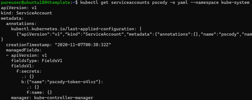
Create a Service Account
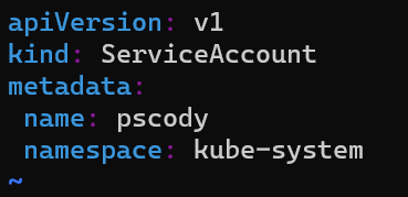
So the first step is to create a service account. So create a new file and then in that, enter in the following information, replacing the username and/or namespace with whatever you want:
vim newuseracct.yml
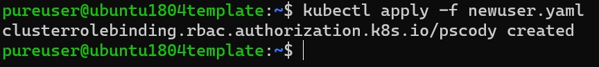
Then apply it:
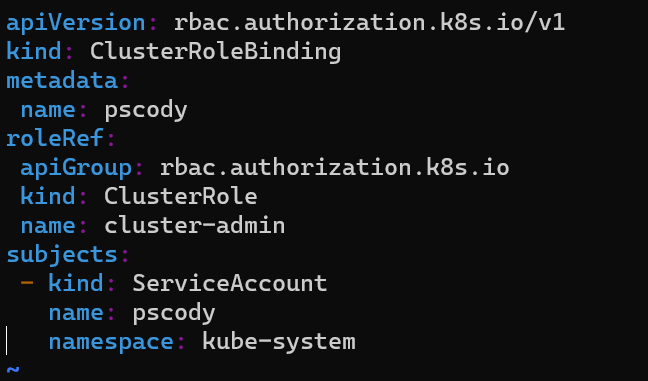
Again using your favorite editor, create a new file:
vim newuser.yaml
This will apply the cluster admin role to that account. Replace the username, the namespace or even role as needed.
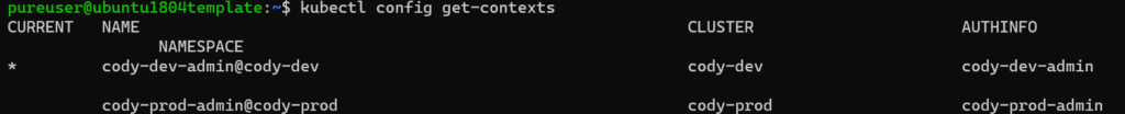
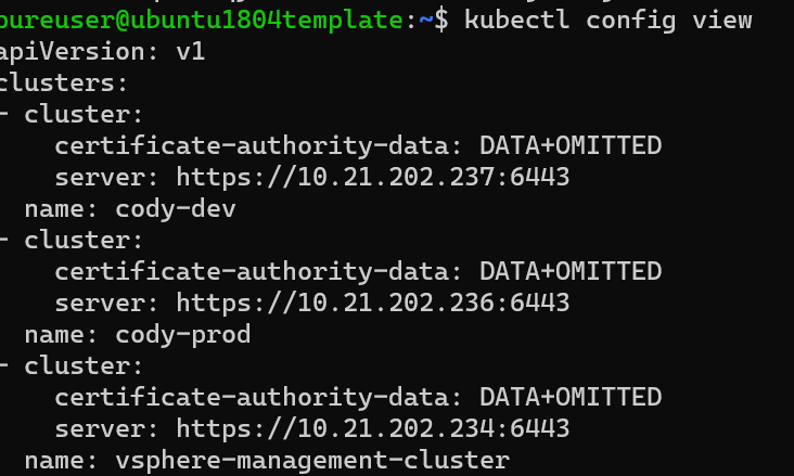
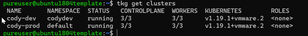
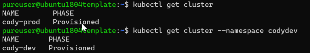
Now you need to get the server address for the cluster where you created the user. So if you don’t know, look at the context via kubectl config get-contexts:
Then, run kubectl config view and pull the server address for the corresponding cluster, so for mine it is cody-dev so the address is https://10.21.202.237:6443
Connect with Invoke-RestMethod
Now head over to PowerShell!
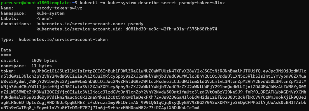
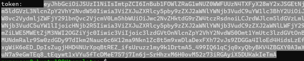
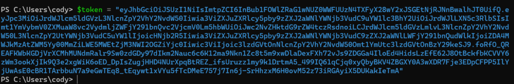
First, store your token in an object, I will use $token.
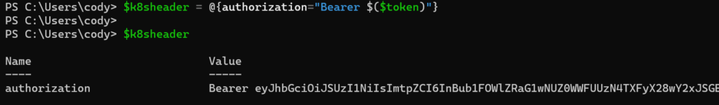
Then we need to form the header as a bearer token:
$k8sheader = @{authorization="Bearer $($token)"}
This is the format needed to authenticate with that token.
Now you are ready!
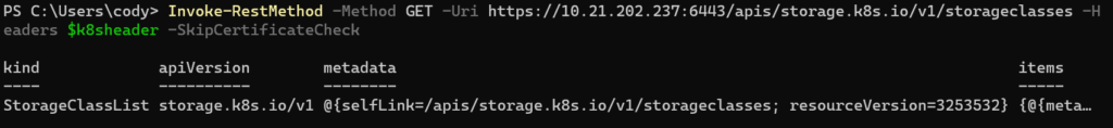
To pull the storage classes for instance run:
Invoke-RestMethod -Method GET -Uri https://10.21.202.237:6443/apis/storage.k8s.io/v1/storageclasses -Headers $k8sheader -SkipCertificateCheck
You will need skip certificate check for now–I didn’t configure the certificate checking yet.
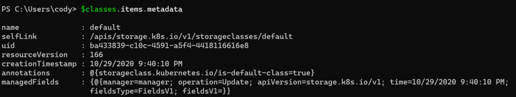
If we store the response in an object we can more easily dig in:
And find my default storage class.
Definitely a lot more for me to learn here, but it is a start!
JSON Web Tokens (JWT) are part of the mechanism that we (and many modern REST implementations) use to authorize connections. I think the term authorize is the key here. Authenticate vs. Authorize. Think of it in a similar way to when you log into a website. You initially login (authenticate) with a website with a user name and password. But the next time you go to it, or re-launch your browser you don’t have to. Why because you already authenticated. An authorization is stored in a cookie so you don’t have to again. For at least a certain amount of time or for the length of that browser session etc.
This is often somewhat abstracted, but not always. If you want to directly authenticate to Pure1, for instance, you need to create a JWT. So let’s dig into that process. Then let’s talk about troubleshooting techniques for a rejected JWT.
The Anatomy of a JWT
So what is in a JWT? Well the data can vary, but in this case I will be talking about the data required by Pure1.
There are three parts:
Headers
Payload
Signature
The headers indicate what type of encryption is used in the signature.
The payload indicates the information required by the authenticator. Expiration. User. Key. Whatever.
The signature is the encrypted string that consists of the header plus the payload data. So an example.
For Pure1, the header looks like so. Always:
{
  "alg": "RS256",
  "typ": "JWT"
}
Basically saying use RSA 256 bit encryption for this JWT.
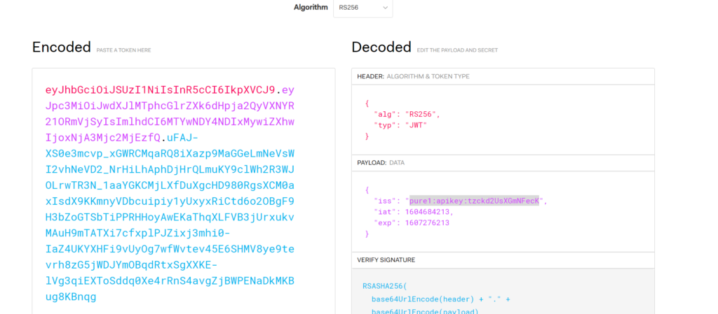
The payload is always structured the same, but the data varies:
The iss property is a Pure1 key assigned to an application. The IAT property is the current epoch time, and the exp property is the expiration of this key. So the JWT cannot be used after that time to authorize any more connections.
As you might notice, this information is formatted in JSON. But it is not sent that way. The data is sent via https, so it needs to be what is called URL encoded.
There is a third section. This is the first two parts that have been encrypted via a RSA 256 bit private key.
So basically the header and payload is sent twice. Unencrypted, but URL encoded and encrypted AND URL encoded.
A good way to decode this is via a website jwt.io.
This site will interpret the unencrypted, but URL encoded data and display them in the right hand side.
How Pure1 checks the JWT
So how does Pure1 check the JWT? Well a few things happen. Before a JWT can be used for authorization, you must first create a RSA 256 bit private key. Let’s say our key is this:
This key is used to create the signature portion of the JWT. More on that in a bit.
From the private key, a public key is created. This is used to decipher anything signed by the private key. So a public key for the above private key is the following:
-----BEGIN PUBLIC KEY-----
MIIBIjANBgkqhkiG9w0BAQEFAAOCAQ8AMIIBCgKCAQEA4WVi9HtenBdPUbZKvjOo
efYxUsNOt+eUTPAMWU3dNoUR/2pkoy1i2+iOBwkQgh5veyKZpQQCjEnyGKeliZEk
MPh2bJgFuKKyG4L0wgU1v7AEsuhQoNg7mdpPUlmIiIkVU91mtLxjES95AXl0A0oj
kUFe5JsE71Qt+2GgVJoB7fRh2l8eQnvje9tcfGFaAKoW63FmalNrZq8FjDbhQ4N3
AFANClfRlP7Ru3QLGbPWl3WMdGkjZU7STYON3fg3TN7K/95xRheOqpbZ/JpL9FHr
wZNiSx4hY82pjqDrdeF2mGDVILMa3FQIHNBqNyY1ORkLc8EW+wKJk+8OsNwbr4mj
WwIDAQAB
-----END PUBLIC KEY-----
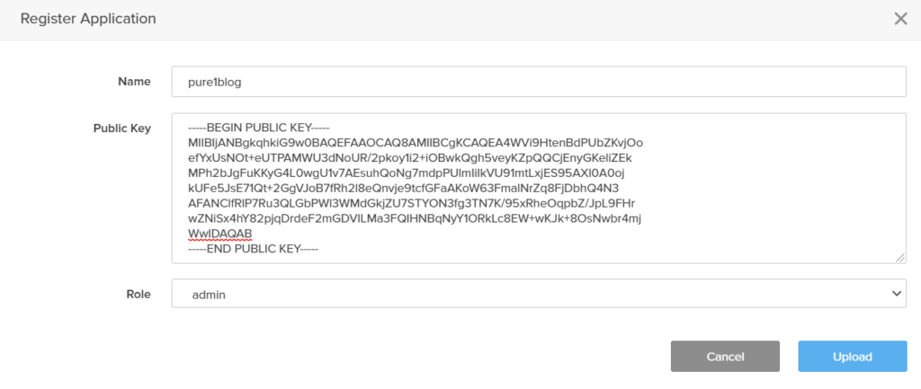
So the public key is entered into Pure1.
Once uploaded, Pure1 generates an Application ID that corresponds to that public key.
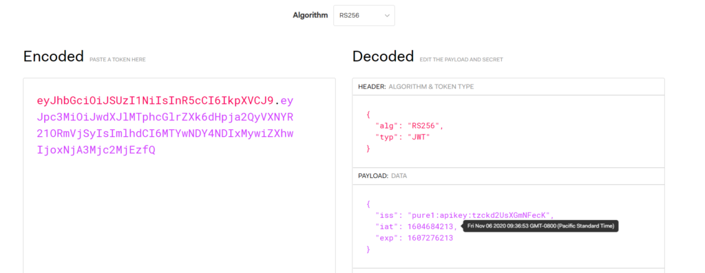
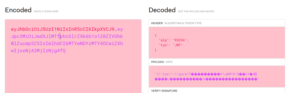
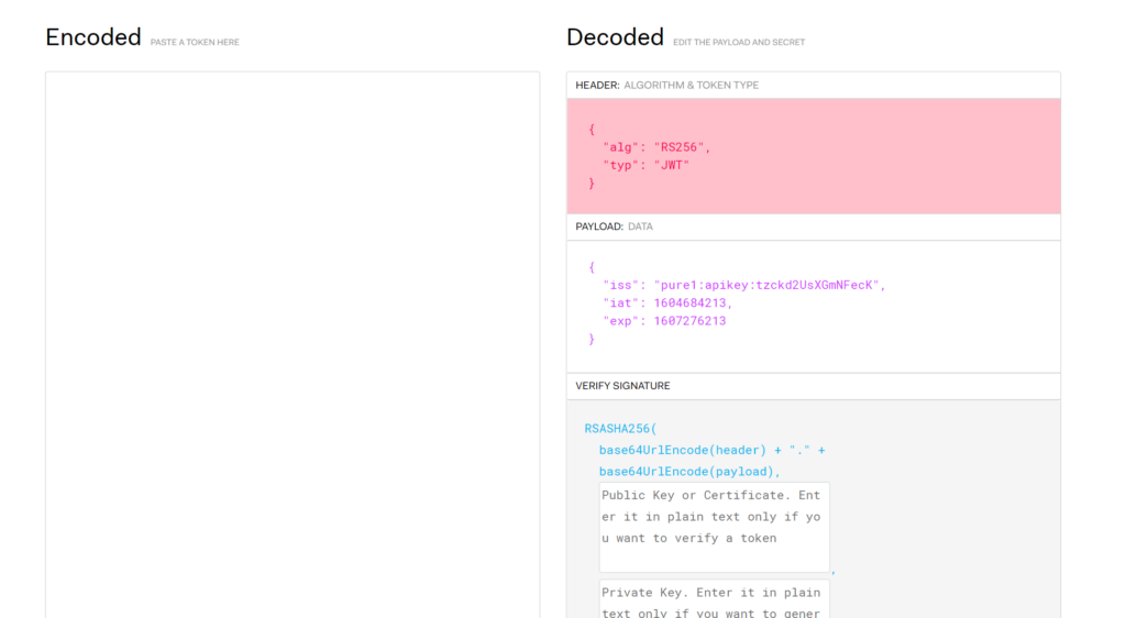
Navigate the the website jwt.io. Paste the first two parts of the JWT into the left panel:
This will automatically decode them into the header and payload. If it looks different or weird:
It is formatted incorrectly or encoded incorrectly. If it is formatted correctly, the main thing you want to check here, is that the API key is correct.
Verifying the Public Key
Next the signature itself.
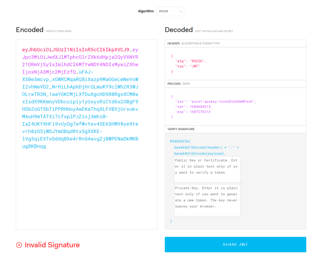
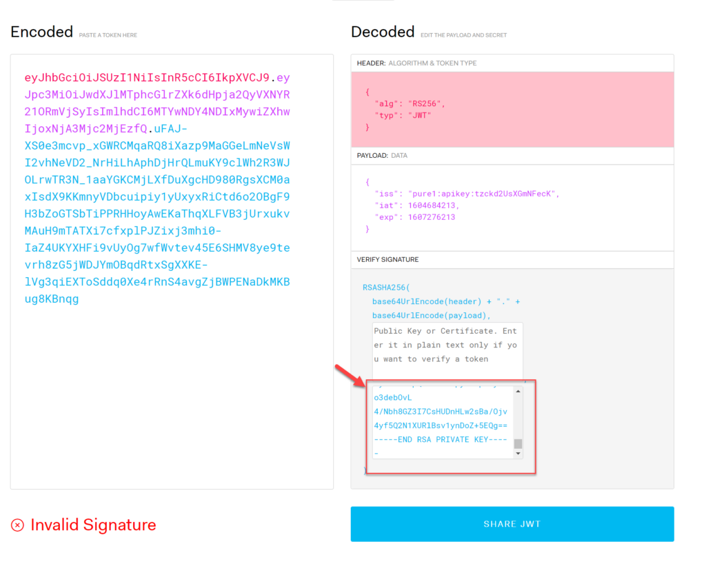
Now paste the FULL JWT into the left panel:
Note that the signature is noted as invalid. This is because there is no key to check it with. For this you need the public key.
My public key is the following:
-----BEGIN PUBLIC KEY-----
MIIBIjANBgkqhkiG9w0BAQEFAAOCAQ8AMIIBCgKCAQEA4WVi9HtenBdPUbZKvjOo
efYxUsNOt+eUTPAMWU3dNoUR/2pkoy1i2+iOBwkQgh5veyKZpQQCjEnyGKeliZEk
MPh2bJgFuKKyG4L0wgU1v7AEsuhQoNg7mdpPUlmIiIkVU91mtLxjES95AXl0A0oj
kUFe5JsE71Qt+2GgVJoB7fRh2l8eQnvje9tcfGFaAKoW63FmalNrZq8FjDbhQ4N3
AFANClfRlP7Ru3QLGbPWl3WMdGkjZU7STYON3fg3TN7K/95xRheOqpbZ/JpL9FHr
wZNiSx4hY82pjqDrdeF2mGDVILMa3FQIHNBqNyY1ORkLc8EW+wKJk+8OsNwbr4mj
WwIDAQAB
-----END PUBLIC KEY-----
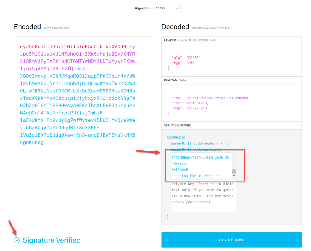
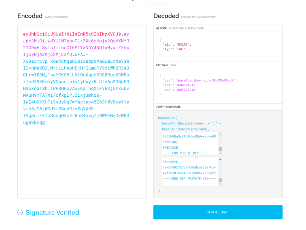
Take that and paste it into the public key box. If this is the right public key, it will turn to signature verified. If it does not, you are using the wrong public key. In this case
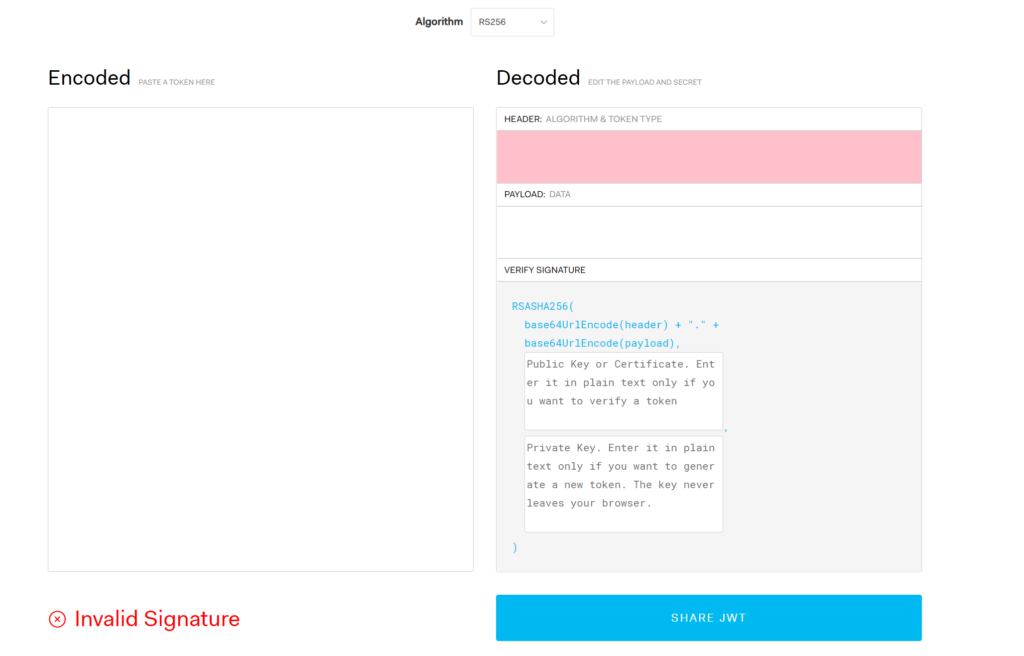
It will create the JWT for you. If that JWT is different than one you generated elsewhere your other JWT was incorrectly created.
You can add in your public key to ensure it is all good:
What to do with a bad JWT
So if you get an authorization error with Pure1 what should you do? Make sure the combination that you are using is correct: right API key, right public key, right private key. Figure out which one is wrong. The simplest thing often is to start over: create a new key pair, add the public one into Pure1, and retry.
The next step here is storage. I want to configure an ability to provision persistent storage in Tanzu Kubernetes. Storage is generally managed and configured through a specification called the Container Storage Interface (CSI). CSI is a specification created to provide a consistent experience in an orchestrated container environment for storage provisioning and management. There are a ton of different storage types (SAN, NAS, DAS, SDS, Cloud, etc. etc.) from 100x that in vendors. Management and interaction with all of them is different. Many people deploying and managing containers are not experts in any of these, and do not have the time nor the interest in learning them. And if you change storage vendors do you want to have to change your entire practice in k8s for it? Probably not.
So CSI takes some proprietary storage layer and provides an API mapping:
Vendors can take that and build a CSI driver that manages their storage but provides a consistent experience above it.
At Pure Storage we have our own CSI driver for instance, called Pure Service Orchestrator. Which I will get to in a later series. For now, lets get into VMware’s CSI driver. VMware’s CSI driver is part of a whole offering called Cloud Native Storage.
This has two parts, the CSI driver which gets installed in the k8s nodes, and the CNS control plane within vSphere itself that does the selecting and provisioning of storage. This requires vSphere 6.7 U3 or later. A benefit of using TKG is that the various CNS components come pre-installed.
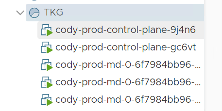
So in the previous post, I wrote about deploying a Tanzu Kubernetes Grid management cluster.
VMware defines this as:
A management cluster is the first element that you deploy when you create a Tanzu Kubernetes Grid instance. The management cluster is a Kubernetes cluster that performs the role of the primary management and operational center for the Tanzu Kubernetes Grid instance. This is where Cluster API runs to create the Tanzu Kubernetes clusters in which your application workloads run, and where you configure the shared and in-cluster services that the clusters use.
In other words this is the cluster that manages them all. This is your entry point to the rest. You can deploy applications in it, but not usually the right move. Generally you want to deploy clusters that are specifically devoted to running workloads.
These clusters are called Tanzu Kubernetes Cluster. Which VMware defines as:
After you have deployed a management cluster, you use the Tanzu Kubernetes Grid CLI to deploy CNCF conformant Kubernetes clusters and manage their lifecycle. These clusters, known as Tanzu Kubernetes clusters, are the clusters that handle your application workloads, that you manage through the management cluster. Tanzu Kubernetes clusters can run different versions of Kubernetes, depending on the needs of the applications they run. You can manage the entire lifecycle of Tanzu Kubernetes clusters by using the Tanzu Kubernetes Grid CLI. Tanzu Kubernetes clusters implement Antrea for pod-to-pod networking by default.
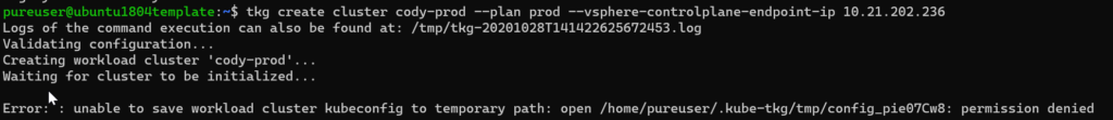
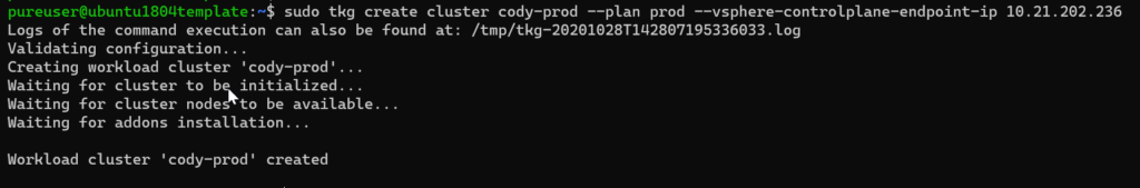
The VMs were all deployed and good, but it looks like it did not quite have the permissions to save the information to my local config. This is likely salvageable, but since it is new, just as simple to delete it and re-run with sudo
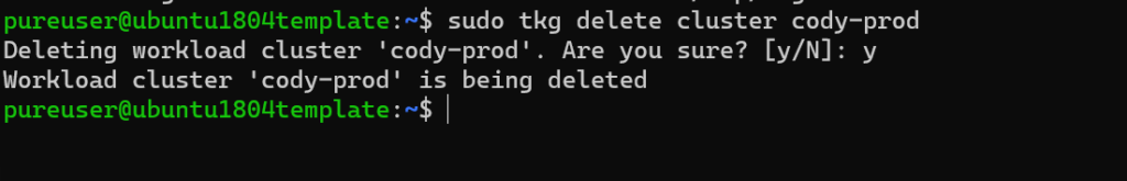
sudo tkg delete cluster cody-prod
Deletes the VMs and removes the references. The likely solution here is folder permissions, but for now just use sudo with tkg when provisioning new resources.
I wrote awhile back on how to deploy TKG on top of vSphere, but there have been some improvements, some changes, and I have personally learned more so I thought it was time to write a new one.
The process requires a few things, but first the deployment of the management cluster–and there are a few options for this. A burgeoning option is the more integrated version to vSphere, which is called Tanzu Kubernetes Grid Service. This means the supervisor cluster is tightly integrated into vSphere. This comes in two forms vSphere with Tanzu or VMware Cloud Foundation (VCF) with Tanzu. The latter is the most feature rich but of course requires VCF and NSX. The former doesn’t quite have all of the options, but does not require those two, instead just vSphere and virtual distributed switches.
The third option is to deploy the management cluster directly. This has the least requirements, but has the least direct integration into vSphere. This is what I will focus on today. I will follow up with the other options. This choice is generally just called Tanzu Kubernetes Grid.
The recent release of VMware Cloud Foundation (version 4.1) added support for Virtual Volumes as a principle storage option via either iSCSI or Fibre Channel. See some more information on that here:
When you deploy a new workload domain in VCF, a new vCenter gets deployed and along with that a new cluster with hosts, and all of the various related pieces (NSX etc.). Before you can deploy a WD, you must have of course hosts–and ESXi needs to be installed on these hosts. Depending on what storage option you choose, there are a few requirements for these hosts besides just having ESXi.
Note: This is another guest blog by Kyle Grossmiller. Kyle is a Sr. Solutions Architect at Pure and works with Cody on all things VMware.
In VMware Cloud Foundation (VCF) version 4.1, vVols have taken center stage as a Principal Storage type available for Workload Domain deployments. This inclusion in one of VMware’s premier products reinforces the continued emphasis on vVols and all the benefits that they enable from VMware. vVols with iSCSI is particularly exciting to us as this is the first instance of the iSCSI protocol being supported as a Principal Storage type within VCF. We at Pure Storage are honored to have had a little bit of influence over this added functionality by serving as a design partner for this new feature and we are confident you are going to like what you see!
Someone who is using VMFS datastore with VCF today might ask themselves ‘why vVols’? This is a great question deserving of an expansive answer beyond this blog post. Fundamentally, though, using vVols enables you to fully use the FlashArray in the way it was intended. By leverage VASA (VMware API for Storage Awareness) you gain far more granular control and monitoring abilities over your individual VMs. Native FlashArray capabilities such as snapshots and replication are directly executed against the underlying array via policy-driven constructs. Further information on these and other benefits with vVols are available here.
Using vVols as Principal Storage is a lot like the methods VCF customers are used to for pre-existing Principal Storage options. Image an ESXi host, apply a few prerequisites to it, commission it to SDDC manager and create Workload Domains. Deploying Workload Domains with VMware Cloud Foundation automates and takes all the guesswork out of deploying vCenter and NSX-T for modern use cases such as Kubernetes via Workload Management.
Stepping into some specifics for a moment; here’s the process on how to use FlashArray iSCSI and vVols for VCF Workload Domains:
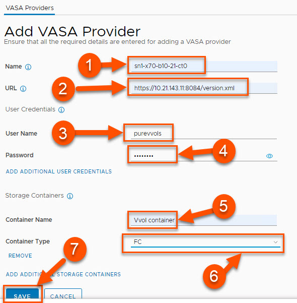
The most fundamental update to SDDC Manager to allow vVols is the capability to register a VASA Provider. In the below screenshot and following detailed information, we show an example of how you can add a FlashArray using another block protocol: Fibre Channel:
Provide a descriptive name for the VASA provider. It is recommended to use the FlashArray name and append it with -ct0 or -ct1 to denote which controller the entry is associated with.
Provide the URL for the VASA provider. This cannot be the management VIP of the array. Instead this field needs to be the management IP address associated with one of the controllers. The URL also is required to have the VASA port and version.xml appended to it. The format for the URL is: https://<IP of FlashArrayController>:8084/version.xml
Give a FlashArray user name with the arrayadmin role. The procedure for how to create such a user can be found here. While the pureuser account can be used, we recommend creating and using a separate FlashArray user for VASA operations.
Provide the password for the FlashArray username to be used.
Container Name must be Vvol container. Note that this value is case-sensitive.
For Container Type, select FC from the drop-down menu to use Fibre Channel.
Once all entries are completed, click Save.
Obviously, there’s a lot more to share here so we will be expanding on this substantially in the very near future on our VMware Platform Guide site.
Rounding out this post, I’m happy to show a demo video of just how easy it is to deploy a FC+vVols-based Workload Domain with VMware Cloud Foundation.
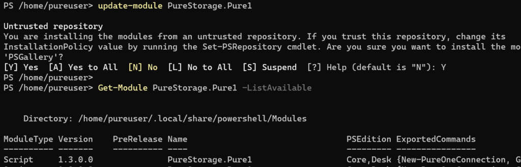
Just pushed out a new release of the Pure Storage Pure1 PowerShell module. Not nearly as significant of a release as 1.2.0.0, but still a couple of notable things.
As usual update with update-module PureStorage.Pure1:
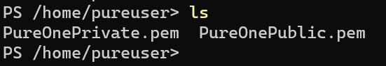
The first update is simplified authentication. The first time you authenticate, you need to run New-PureOneCertificate–on Windows this will create a self-signed x509 certificate, and if run on Linux or Mac it will create an RSA key pair. By default it will store it in the user directory first logged into when running PowerShell core: